Your browser does not support JavaScript!
Skip to content Skip to navigation menu

Group Safety Standards IEC60204-1: 2016 | APAC

1. Positioning of IEC 60204-1

ISO 12100 describes that IEC 60204-1 “Safety of machinery - Electrical equipment of machines - Part 1: General requirements” should be referred to for measures against electrical hazard sources based on results of risk assessments. IEC 60204-1 is an important standard in the area of machine safety that forms the basis to ensure the safety of electrical equipment.

There are three purposes of this standard as follows:
•    Safety of persons and property (including equipment, devices, components, etc)
•    Consistency of control response
•    Ease of operation and maintenance

Its purpose includes not only to prevent persons from getting an “electric shock”, but also to prevent a machine itself, devices to be used, and components of work piece from being damaged due to an “electrical fire” and the like. In addition, the standard is also aimed at ensuring “response to control as intended”, “operability based on the ergonomic principles”, and “ease of maintenance”. The requirements to achieve these goals are described.


The scope of the standard is as follows.
•    Electrical, electronic and programmable electronic equipment and systems used for machines not portable by hand while working (including a group of machines working together in a coordinated manner)
•    Inside of the electrical equipment of the machine from the connection point of the electrical supply
Electrical equipment that operates with nominal supply frequencies not exceeding1000 V AC/1500 V DC and with nominal supply frequencies not exceeding 200 Hz


This standard does not specify additional and special requirements that can apply to the electrical equipment of machines that, for example:
•    Machines to be used in open air (outside of buildings or other protective structures)
•    Machines that use, process, or produce potentially explosive material (paint, sawdust, and so on)
•    Machines intended for use in potentially explosive and/or flammable atmosphere
•    Machines at special risk when a certain material is used or produced
•    Machines intended for use in mines
•    Sewing Machines, units, and systems (specified in IEC 60204-31)
•    Hoisting machines (cranes, hoists, and the like, specified in IEC 60204-32)
•    Semiconductor fabrication equipment (specified in IEC 60204-33)

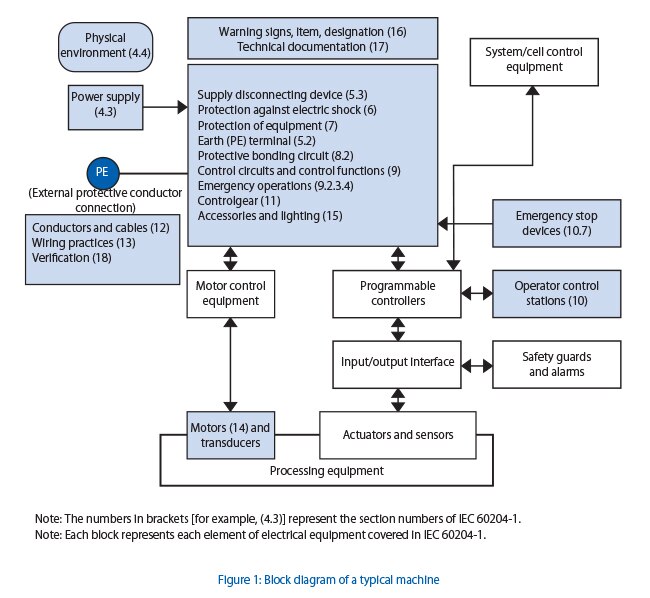
Figure 1 shows the sections relevant to this standard.

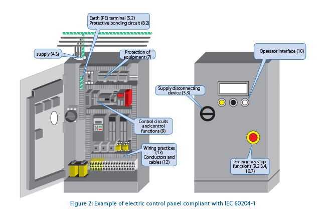
In Figure 2, Figure 1 is applied to an electric control panel.

2. Voltage range and operating environment

First, electric parts and electric equipment to be used shall satisfy the following.
•    Suitable for the intended usage
•    Conform to the relevant IEC standards, if applicable
•    Used in accordance with the supplier’s instructions

In addition to satisfying the above, the electrical equipment shall be correctly operated under the following conditions.


Voltage range (4.3)

The electrical equipment shall be correctly operated under either of the following electrical supply conditions.

AC supplies (4.3.2)

Voltage:  Steady state voltage: 0,9 to 1,1 of nominal voltage 
Frequency: 0,99 to 1,01 of nominal frequency continuously or 0,98 to 1,02 short time.
Voltage interruption: Supply interrupted or at zero voltage for not more than 3 ms at any random time in the supply cycle with more than 1 s between successive interruptions. 

DC supplies (4.3.3)

Voltage: 0.85 to 1.15  of nominal voltage. For battery  operated vehicles, 0.7 to 1.2  of nominal voltage
Voltage interruption: 5 ms or less


Converting equipment 
Voltage: 0.9 to 1.1  of nominal voltage
Voltage interruption: Not exceeding 20 ms with more than 1 s between successive interruptions.  

Ambient temperature (4.4.3)

As the minimum condition, the equipment shall be correctly operated when the ambient temperature outside the enclosure is between 5°C and 40°C. 

Humidity (4.4.4)

The equipment shall be correctly operated when the relative humidity is 50% or less at the maximum ambient temperature of +40°C. If the temperature is lower, a higher humidity may be acceptable (for example, 90% at +20°C).
 

Altitude (4.4.5)

The electrical equipment shall be correctly operated at an altitude of 1,000 m or lower above sea level.
For equipment to be used at higher altitudes, it is necessary to take into account the reduction of: 
•    Withstand voltage
•    Switching capability of devices
•    Air cooling effect

Transportation and storage (4.5)

The equipment shall be designed to withstand from -25°C to +55°C for a long period and up to +70°C for a short period, 24 hours or less, during transportation and during storage, or appropriate measures against extreme temperatures shall be taken. 

3. Connection with the electrical supply of the factory

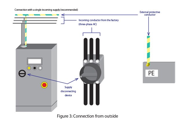
To connect the input  supply conductor with the electrical equipment of the machine, such as a control panel, the supply conductors are terminated at the supply disconnecting device  or a plug (socket outlet) is used. At that time, it is recommended that the machine is connected to a single incoming supply.

Requirements for supply disconnecting devices (IEC 60947-3 is one of applicable standard)

It is necessary to install a supply disconnecting device for each  incoming supply for the machine and each  on-board power supply mounted on the machine. (5.3.1)
Supply disconnecting devices serve to disconnect the electrical supply of the factory from the inside of the control panel, for example, when maintenance person open the control panel and perform some kind of maintenance. By this measure, the maintenance personnel can perform the maintenance without being exposed to electrical hazard sources. Since the supply disconnecting devices have such an important role, they shall satisfy all of the following requirements.

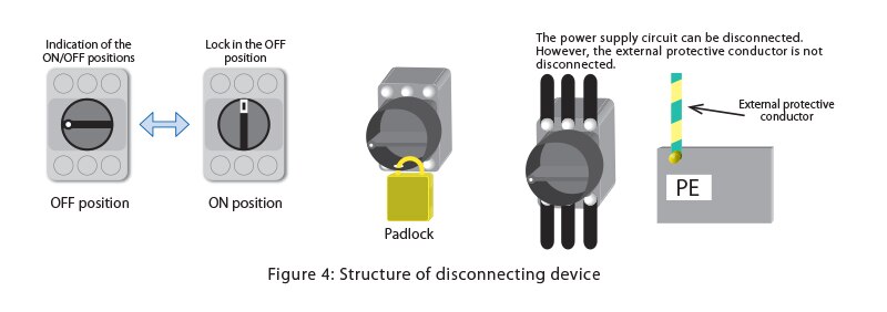
•    The positions of OFF (disconnected) and ON (closed) shall be marked with symbols “○” and “|”, respectively.
•    Gap between the contacts can be visually observed. Alternatively, the device has a position indicator that cannot display OFF (disconnected) until the supply conductor is disconnected.
•    The device has a  operating means  (for example, a handle)  external to the enclosure. If it is not intended for emergency operations, black or gray is recommended for the color of the handle. If it is intended for emergency operations, the color of the handle shall be red with yellow background.
•    The device is equipped with a measure (for example, a padlock) to lock the position at OFF (disconnected).
•    All charging conductors of the power supply circuit can be disconnected.
•    The breaking capacity of the device have sufficient to interrupt the current of the largest motor when stalled together with the sum of the normal running currents of all other motors and other loads. 
 

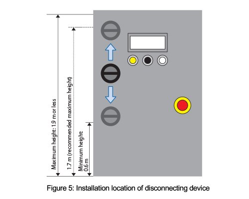
•    The operating mean of a supply disconnecting device shall be provided at an easily accessible location between 0.6 m and 1.9 m above the  servicing level. The recommended maximum height is 1.7 m.


Excepted circuit:

An excepted circuit is a circuit that may not be disconnected with a supply disconnecting device for securing safety in the event of problem or during maintenance. The following can be considered to be an excepted circuit.

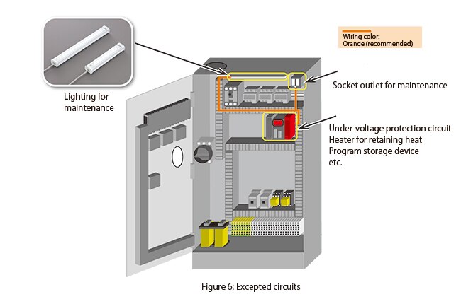
▶  Power supply circuit for lighting required for maintenance or repair
▶ Socket outlet for the exclusive connection of repair or maintenance tools and equipment (for example hand drills, test equipment) 
▶ Under-voltage protection circuit that are only provided for automatic tripping in the event of supply failure
▶ Circuit supplying equipment that should normally remain energized for correct operation (for example temperature controlled measuring devices, heaters, program storage devices). 
 

However, it is recommended that such circuits be provided with their own disconnecting device. 
 

4. Protection against electric shock

Electrical facilities  shall provide measures of protection against an electric shock due to contact of a human body or a body part with a live part of electrical equipment.
In IEC 60204-1, a live part is defined as “conductor or conductive part intended to be energized in normal use, including a neutral conductor, but, by convention, not a PEN conductor (3.1.38)”.
There are two types of electric shocks and they are defined as follows.

•    Direct contact (3.1.15): contact of persons or livestock with live parts 
Indirect contact (3.1.34): contact of persons or livestock with exposed conductive parts (Note 1) which have become live under fault conditions  
Note 1: Conductive part of electrical equipment, which can be touched and which is not live under normal operating conditions, but which can become live under fault conditions 
 

The protective measures against the electric shocks described above are defined as follows.
•    Basic protection (3.1.4): protection against an electric shock (due to direct contact) under fault-free conditions (insulation failure).
•    Fault protection  (3.1.31): protection against an electric shock (due to indirect contact) under single-fault conditions 

In IEC 60204-1, these protection measures are categorized as shown in Table 1 below.
Table 1: Methods of protection against electric shock
Basic protection(6.2)Protection by enclosure(6.2.2)
Protection by insulation of live parts(6.2.3)
Protection against residual voltages(6.2.4)
Protection by barriers(6.2.5)
Protection by placing out of reach or protection by obstacles(6.2.6)
Fault protection(6.3)Prevention of the occurrence of a touch voltage(6.3.2)Protection by provision of class II equipment or by equivalent insulation(6.3.2.2)
Protection by electrical separation(6.3.2.3)
Protection by automatic disconnection of supply(6.3.3)a)TN systems
b)TT systems 
c)IT systems 
Protection by the use of PELV(6.4)

In the basic protection, to prevent an electric shock due to direct contact of workers with a live part when the machine is operating normally, measures are taken such as “to cover with an enclosure ” and “to keep a distance”.

In the fault protection , to prevent workers from getting an electric shock due to an exposed conductive part that has become a live part in the event of an insulation failure, either of the following measures is taken: “to ensure that no live part occurs due to an insulation failure in the first place” or “to automatically interrupt the electrical supply with an overcurrent protective device or an earth leakage breaker if an exposed conductive part becomes a live part”.

In the protection using a PELV, measures are taken to protect a person from an electric shock due to indirect contact or direct contact with a limited direct contact area.
 

5. Protection of equipment

Refers to measures of preventing breakdown of the equipment and electrical fire due to overcurrent or temperature rise. Typical measures include protection of equipment by using an overcurrent protective device.

If the circuit current in the electrical equipment could exceed either of the rated value of a component or the allowable current of the conductor, whichever is smaller, an overcurrent protective device shall be used (7.2.1).


The overcurrent protective device is required for the following.
•    Supply conductors (7.2.2)
•    Power circuits (7.2.3)
•    Control circuits (7.2.4)
•    Socket outlets and their associated conductors  (7.2.5)
•    Lighting circuits (7.2.6)
•    Transformers (7.2.7)

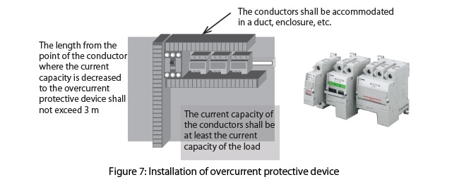
In addition, the conditions regarding installation of the overcurrent protective devices are shown below. Unless all of the following conditions are satisfied, an overcurrent protective device shall be installed.
•    The current capacity of all conductors shall be at least equal to or greater than the current capacity of the load.
•    The length from the conductor where the current capacity is decreased to the overcurrent protective device shall not exceed 3 m.
•    The conductors shall be installed in such a way that the possibility of short circuit is low (for example, protection using a duct or enclosure).

6. Equipotential bonding

An equipotential bonding is “provision of electric connections between conductive parts, intended to achieve equipotentiality  (3.1.26)”, including the protective and functional bonding.

The protective bonding is “ equipotential bonding for protection against electric shock (3.1.49)”, while the functional bonding is “equipotential bonding necessary for proper functioning of electrical equipment (3.1.32)”.
As it is described in the  standard that “Protective bonding is a basic provision for fault protection to enable protection of persons against electric shock”, the protection bonding plays an important role especially when an insulation failure occurs.

A protective bonding circuit is configured with interconnection of the following. (8.2.1)
● PE terminal (terminal for connecting the external protective conductor)
● Protective conductor inside the  equipment of machine (note)
Note: A conductor that serves as the primary fault current path from the exposed conductive part to the protective earth (PE) terminal of the electrical equipment.
● The conductive structure part and the exposed conductive part of the electrical equipment
● The conductive structure part of the machine

By interconnecting these, protect a person from electric shock due to a ground fault and earth leakage in the event of an insulation failure.

Note that, if an earth fault  occurs, a large current may pass through the protective conductor. Therefore, the protective conductor shall be able to withstand thermal stress due to a large current. In addition, it is also necessary to prevent mechanical damage to the protective conductor in order to secure the conductivity of the protective bonding circuit.
 

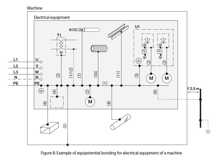
Protective bonding circuit
(1)Interconnection of the protective conductor and the PE terminal
(2)Connection of the exposed conductive part
(3)Protective conductor connected to an electrical equipment mounting plate used as a protective conductor
(4)Connection of the conductive structure part of the electrical equipment
(5)The conductive structural part of the machine
The part that shall be connected with the protective bonding circuit (shall not be used as a protective conductor)
(6)Metal duct of  a flexible or rigid construction 
(7)Metallic cable sheath or armoring 
(8)Metallic pipes containing flammable materials
(9) Extraneous conductive parts. if earthed independently from the power supply of the machine and liable to introduce a potential, generally the earth potential.For example, a metallic pipe , fence, ladder, and handrail.
(10)Metal conduit that is flexible or pliable (can be molded manually)
(11)Protective bonding of the support wires, cables tray, and cable ladders
Connection to the protective bonding circuit for  functional reason
(12)Functional bonding
Legend to reference designations 
T1Auxiliary transformer
U1Mounting plate for the electrical equipment


The contacts of the protective conductors require one of the following labels or indications.

•    Symbol:
•    Letters “PE” (the graphic symbol is preferred)
•    Combination of two colors: green and yellow
•    Combination of the above

Note that, for the connection points of the functional bonding, it is recommended to mark the symbol:

7. Control circuits and control functions

As described in the purposes of IEC 60204-1, it is important for safety to secure the consistency of control response. Accordingly, the following requirements exist.
•    Supply voltage of the control circuit
•    Stop and operation as the control functions

If the control circuit is supplied with AC, a transformer shall be used for the control circuit.
This transformer shall  have a separate windings . (9.1.1)
In addition, the control circuit voltage should not exceed the following values. (9.1.2)

AC control circuit
- Nominal frequency 50 Hz, 230 V
- Nominal frequency 60 Hz, 277 V

DC control circuit
- Nominal voltage 220 V


As mentioned in “5. Protection of equipment”, the control circuit shall be provided with an overcurrent protective device. (9.1.3)

The control functions typically include the following.

Start functions (9.2.3.2)

The start functions of the machine shall be operated by energizing the machine. The machine shall be able to be started only when the safety functions and/or the protective measures are in place and are operational.

Stop functions (9.2.3.3)

The stop functions shall override related start functions. The stop functions are classified into the three stop categories as follows. It is necessary to select one of the stop categories according to the risk assessment and/or the functional requirements of the machine.

Table 2: Stop categories
Stop categoriesCommon name for controlISO14118
 
Description of stop stateExample of stop state
0Uncontrolled stopStop stateStop by immediately disconnecting the power of the mechanical actuatorEmergency stop
1Controlled stopControlled stop where the machine is stopped while the mechanical actuator can use the power, and the power is disconnected after the stop is completed Reverse phase stop
2 Controlled stop with power remainingControlled stop where the power is still supplied to the mechanical actuator after the stop is completed.Hold stop

Operation mode (9.2.3.5)

Each machine can have operation modes according to its type and usage (for example, the manual, automatic, teaching and maintenance modes).
If the safety measures and their effect are different in each operation mode, a mode switching device (for example, a key switch) that can be locked at each position of the mode shall be used. In addition, the selected mode shall be clearly identifiable. Instead of the mode switching devices, other selecting methods (for example, access codes) that restrict the use of specified functions to the exclusive operators may be used.
Mode selection by itself shall not initiate machine operation. 


Emergency stop (9.2.3.4.2)

• An emergency stop shall function either as a stop category 0 or as a stop category 1..
• In all modes, it shall override all the other functions and operations.
• It shall quickly stop any dangerous movement as soon as possible without producing other hazard sources.
• The machine shall be designed in such a way that it shall not restart with release of the emergency stop.

Note that other requirements are described in ISO 13850 “Safety of machinery — Emergency stop function — Principles for design”. Check the explanation as well from the following link.

Enable device

A supplementary manual control device used in combination for the start control, enabling the machine to start only when the device is operated continuously.
(the startupis performed with other devices).

Interlock device

Mechanical, electrical, or other type of devices, the purpose of which is to prevent the operation of hazardous machine functions under specified conditions.

Note that other requirements are described in ISO 14119 “Safety of machinery — Interlocking devices associated with guards — Principles for design and selection”. Check the explanation as well from the following link.

Cableless control (CCS)

Control that uses radio, infrared and the like to communicate commands and signals. Since no cable exists, it is necessary to clarify the target of the control in order to avoid an unintended dangerous situation where it is unknown which machine will start moving.
In addition, if it is made possible to simultaneously operate the machine from multiple points, the machine may not be operated as intended by the operator due to an intervention by another person, causing a dangerous situation for the operator. Therefore, the “single point control” where the machine is controlled from a single point is required. In addition, it is necessary to avoid any dangerous situation when the communication of the control commands and signals is interrupted or when the communication is restored.

Control function in case of failure

If a hazardous situation may occur or if the machine or a work piece being processed may be damaged due to failure in the electrical equipment or interference, the electric control system is required to have appropriate capabilities determined based on the risk assessment of the machine.
Regarding the safety-related control functions, it is necessary to apply the requirements in ISO 13849-1 and IEC 62061.
Note that an explanation of ISO 13849-1 “Safety of machinery — Safety-related parts of control systems — Part 1: General principles for design” is described in the following link. Check the explanation as well.

8. Operator interface

The control device of the operator interface shall minimize the possibility of human errors (failed operation due to carelessness) with the arrangement of the equipment, appropriate design, and complementary protective measures. To this end, the ergonomic principles shall be considered.

Colors of actuators

The actuators such as push button switches shall be color coded according to the table below. 

Table 3: Colors of actuators
FunctionColor to useNotes
START/ON white, gray, black, green
White is most preferred
Shall not be used: red
Emergency stop
Emergency switching OFF
Red actuator
Yellow background
STOP/OFFblack, gray, white
Black is most preferred
Shall not be used: green
It is recommended that red is not used near the emergency operation  devices

Alternately switchingSTART/ON and STOP/OFF

white, gray, black Shall not be used: red, yellow, green
Hold to runwhite, gray, black Shall not be used: red, yellow, green
ResetRequired: blue, white, gray, black Shall not be used: green
Reset and STOP/OFF white, gray, black
Black is most preferred
 Shall not be used: green
Control in  abnormal condition , interruption of an automatic cycleYellow


Colors of indicater lights 

 Indicator lights should be colour-coded with respect to the condition (status) of the machine in accordance with the table below.
Table 4: Colors of indictor lights 
ColorMeaningDescriptionAction of operator
RedEmergencyHazardous condition   Immediate response to a hazardous condition  (for example, switching OFF the electrical supply of the machine, caution against the hazardous conditionand escape from the machine)
YellowAbnormalAbnormal
Situation State with imminent danger risk
Monitoring and/or intervention (for example, execute the intended function again)
BlueMandatory  Indication of a condition that requires action by the operatorMandatory  action
GreenNormalNormal condition Optional 
WhiteNeutralOther condition 
 be used whenever doubt exists about
the application of red, yellow, green, or blue
Monitoring

The preferred order of stacked indicating lamps is red, yellow, blue, green, and white from top to bottom.

9. Location, mounting, and enclosure of control gear

For the location and mounting of all control devices (control-gear), the following shall be considered.
•    Ease of access and maintenance
•    Protection against the installation environment or conditions
•    Ease of operation and maintenance of the machine and its associated  devices

The requirements to achieve the above are shown below.

Location and mounting  (11.2)

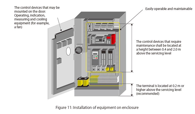
•    All  items of the controlgear  shall be located in such a position and orientation that the parts can be identified without removing the parts or disconnecting the wiring. If it is necessary to check the operation or replace the parts, the check or replacement should be able to be performed without removing other devices or parts.
•    All controlgear shall be mounted in such a way that the control and maintenance can be performed easily.
•    If a special tool is necessary for adjustment, maintenance, or removal of the equipment, the tool shall be provided.
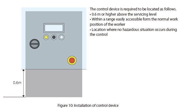
•    The equipment that requires periodic maintenance or adjustment shall be mounted at a height between 0.4 m and 2.0 m above the servicing level .
•    The terminal should be located at least 0.2 m or higher above the servicing level  where the wiring can be easily performed.
•    No devices except devices for operating, indicating, measuring, and cooling shall be mounted on doors or on access covers of enclosures that are expected to be removed. 
•    Where control devices are connected through plug-in arrangements, their association shall be made clear by type (shape), marking or reference designation, singly or in combination. 

Required specifications of enclosures (11.3, 11.4)

•    Protection of equipment against penetration of solids and liquids from the outside shall be appropriate considering the influence from the outside at a location where the machine operation is intended (namely, installation location and physical environment conditions). In addition, adequate protection shall be provided against dust, coolant, sawdust, and so on.
•    The enclosure of the controlgearshall have  a degree of protection of at least IP22 with some exceptions (for the IP protection levels, refer to “Terms and definitions” on page 122).
•    Fasteners used to secure doors and covers should be of the captive type. 
•    Windows of enclosures shall be of a material suitable to withstand expected mechanical stress and chemical attack. 
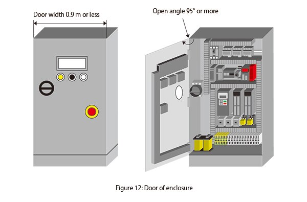
•    Door of the enclosure of the controlgear (recommended)
- Mounted with vertical hinges
- Width: 0.9 m or less
- Open angle: 95° or more

•    If the enclosure is provided with an opening (for example, a cable port), measures shall be provided to secure the required protection level of the equipment.
•    The opening for leading in cables shall be easily opened on site.
•    An appropriate opening may be provided at the bottom of the enclosure in the machine in order to drain dew condensation.

10. Selection of cables

The conductors and cables shall be selected appropriately to the use conditions (for example, voltage, current, protection against electric shock, and density of cables), ambient temperature, presence of water or corrosive substance, mechanical stress, and risk of fire.

Conductor of cables

•    Copper should be used as a conductor (12.2)
•    To secure the required strength, the cross-section area should conform to Table 5 (12.2)
Table 5: Minimum cross section area of copper conductors to maintain adequate mechanical strength
LocationApplicationType of conductor and cable (unit: mm2)
Single coreMulti core
Flexibility class 5 or 6 Solid (class 1) or stranded (class 2)Two core shieldedTwo core not shielded Three or  more cores shielded or not 
Wiring outside (protecting ) enclosure Power circuit (fixed)1.01.50.750.750.75
 Power circuit (moved frequently)1.00.750.750.75
Control circuit1.01.00.20.50.2
Data communication0.08
Wiring inside enclosure (a) Power circuit (fixed)0.750.750.750.750.75
Control circuit0.20.20.20.20.2
Data communication0.08
a) Except special requirements of individual standards. .

Insulation of cables

•    Withstand voltage required for insulation  of cables and conductors (12.3)
- If 50 V AC or 120 V DC is exceeded, testing voltage of 2000 V AC for a duration of 5 minutes
- For PELV circuits, testing voltage of 500 V AC for a duration of 5 minutes


•    The mechanical strength and thickness of insulation  shall  prevent the insulation from being impaired during operation or installation (12.3)

•    For the insulation, it is necessary to consider hazard sources due to flame propagation properties and occurrence of toxic or corrosive haze (12.3)
 

Current-carrying capacity of cables

•    For the current-carrying capacity of cables , consider the main dependency factors as shown below (12.4)
- Cross section area of conductor (conductor resistance)
- Insulation material (maximum allowable temperature and thermal conductivity of insulator)
- Ambient temperature (the current capacity is decreased at a higher ambient temperature)
- Density (the current capacity is decreased at a higher density due to poor heat dissipation)
-  Method of insulation

Cable voltage drop

The cable voltage drop from the electrical supply point to the load shall not exceed 5% of the nominal voltage under normal operating conditions.
 

11. Wiring practices

The cable voltage drop from the electrical supply point to the load shall not exceed 5% of the nominal voltage under normal operating conditions.

Requirements for wiring

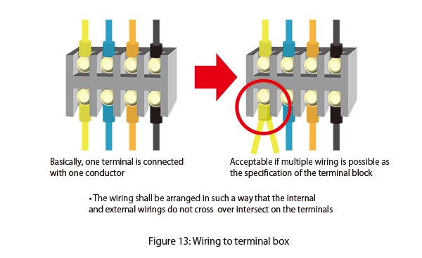
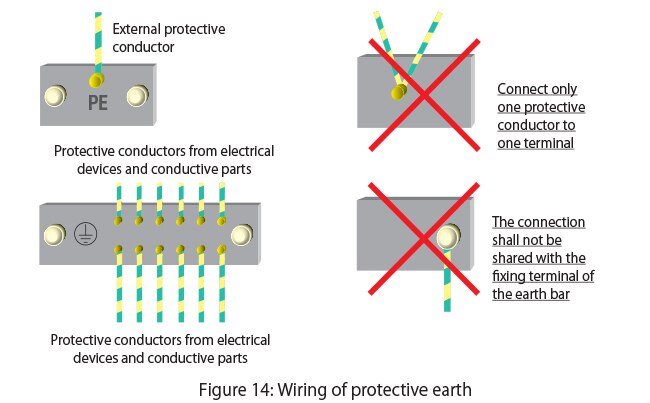
•    Connect one conductor to one terminal
(Except for cases where the terminal is designed to be connected with multiple conductors).

•    For protective conductors, connect only one conductor to one terminal.
•    For terminals of a terminal block, marking or labeling shall be made according to the technical documentation .
•    It is recommended that conductors be identified by number, alphanumeric, colour, or a combination of colour and numbers or alphanumeric. When numbers are used, they shall be Arabic; letters shall be Roman
•    If there is a possible risk due to an erroneous connection, the conductors and the terminals shall be identifiable.
•    The identification tags shall be legible, durable, and suitable for the installation environment.
•    The wiring of the terminal box shall be arranged in such a way that the internal and external wiringsshall not cross over  the terminals.

•    Fix the conductors in the enclosure as necessary
•    For a nonmetallic duct, use a flame retardant insulation material.
•    The wiring of the electrical equipment mounted in the enclosure should be modified from the front. If a control device is connected on the back side of the enclosure, a door or outward opening panel shall be provided.
•    A flexible conductor shall be used for connections to the parts mounted on a door or moving part.
•    The conductors and cables that are not accommodated in ducts shall be appropriately fixed .
•    The wiring for control circuit to the outside of the enclosure shall be connected via a terminal box or a plug and socket combinations .

Colour coding 

The conductors  shall be identifiable using indications or colors.
Colors that can be used: black, brown, red, orange, yellow, green, blue (including light blue), purple, gray, white, pink, and turquoise (blue green)

Table 6: Wiring colors (recommended)
 For power supply  Colour-coding(IEC 60204-1:2005)
AC power circuitBlack (light blue is recommended for neutral conductor)

DC power circuits

Black
Protective conductorCombination of green and yellow  
AC control circuitsRed
DC control circuitsBlue
Excepted circuitsOrange


Protective conductor: a combination of green and yellow (one color covers 30% or more and 70% or less) shall not be used for the wiring other than protective conductors/protective bonding conductors.
Cases where the wiring colors above may not be observed
•    Individual devices that are purchased with their internal wiring completed. When no insulator with the specified color is available.
•    When a multi core cable is used with colors other than the combination of “yellow and green”.

12. Warning signs

Warning signs, nameplates, marking and identification plates shall be of sufficient durability to withstand the physical environment involved.  (16.1) 
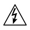
 

For enclosures with built-in electrical equipment at risk of causing electric shock, the graphic symbol on the right shall be displayed.

It is necessary to consider the risk of a hot surface due to the components of electrical equipment that generate heat. The temperature of parts which a person could come in contact shall not exceed the limiting value required in ISO 13732-1.
For the parts where the limiting value may be exceeded, protective measures against unintended contact shall be provided or the graphic symbol on the right shall be displayed.

13. Technical documentation

Information required for nameplates used in the facility
•    name or trade mark of supplier 
•    certification mark or other marking that can be required by local or regional legislation, when required. .
•    type designation or model, where applicable 
•    serial number where applicable 
•    main document number (see IEC 62023) where applicable 
•    rated voltage, number of phases and frequency (if AC), and full-load current for each incoming supply  

The following shall be supplied  as technical documentation
a) where more than one document is provided, a main document for the electrical equipment as a whole, listing the complementary documents associated with the electrical equipment.  


b) Identification of electrical equipment (refer to 16.4)

c) Including the following, information on installation and mounting
•    Description of installation and mounting of electrical equipment and connection to an electrical supply (if applicable, other electrical supplies)
•    Short circuit current rating of electrical equipment of each electrical supply
•    Voltage rating, number of phases and frequency (for AC), type of earthed system (TT, TN, IT), and full load current of each input electrical supply
•    Additional conditions of electrical supply related for each input electrical supply (for example, maximum supply impedance, leakage current)
•    Space required for removal or service of electrical equipment
•    Requirements for installation, if it is necessary to ensure that arrangement for cooling is not impaired
•    Environmental restrictions (for example, lighting, vibration, EMC environment, and airborne contaminants), as necessary
•    Functional restrictions (for example, start peak current and allowable voltage drop), as necessary
•    Precautionary measures related to electromagnetic compatibility required for installation of electrical equipment

d) an instruction for the connection of simultaneously accessible extraneous-conductiveparts in the vicinity of the machine (for example, within 2,5 metres) such as the following to the protective bonding circuit 
•    Metallic pipe 
•    Fence
•    Ladder
•    Handrail

e) Information on the functions and operations including the following (as necessary)
Overview of the structure of electrical equipment (for example by structure diagram or overview diagram))
•    Procedure of programming or configuration required for intended usage
•    Procedure of restart after an unexpected stop
•    Operation sequence

f) Information on maintenance of electrical equipment including the following (as necessary)
•    Frequency and method of function testing
•    Instruction on the procedure to safely perform maintenance, and the procedure to interrupt the safety functions and/or protective measures (refer to 9.3.6)
•    Guide for frequencies and methods of adjustment, repair and preventive maintenance
•    Details of interconnection of electrical devices for replacement (for example, with a circuit diagram and/or connection table)
•    Information on required special devices or tools
•    Information on spare parts
•    Information on possible residual risks, description of necessity of special trainings, and specifications of personal protective equipment if necessary
•    Explanation of restriction limiting use of the keys or tools to only electricians and electrical workers, when applicable
•    Settings (dip switches, programmable parameter values, etc.)