A highly automated production facility, such as the one shown in Figure 1, appears to require no human intervention.
However, as shown in Figure 2, there are many high-risk tasks that are riskier than those during normal operation, such as when people enter the safety fence machine guard (hazard zone) and perform manual operation near the robot arm and other moving parts during equipment startup, changeover, or robot teaching operations. The 3-position enabling switch (hereinafter referred to as “enabling switch”) is effective for ensuring safety in such situations.
Enabling switches are built into portable control devices, such as robot teaching pendants, to allow manual operation of the machine by a human using the enabling switch. This switch is also a safety device that can be used to stop the machine by disabling operation through an immediate reflex reaction when there is imminent danger to people.
Operation and Usage of Enabling Switch
A typical enabling switch is shown in Figure 3, and an example of an enabling device with an embedded enabling switch is shown in Figure 4.
In contrast to the two-position ON/OFF button operation of a typical switch, an enabling switch has three positions of button operation: OFF, ON, and OFF. Figure 5 shows the positions of button operation and the ON/OFF status of their contacts.
Position 1 is the state with no button operation. Since the contact is off, manual operation of the machine is not allowed.
Position 2 is the state when the button is lightly pressed in. The contact is turned on, and manual operation of the machine is allowed. Teaching of the robot can be done in this state only. Note that if you release your hand from position 2, the button will return to position 1, the contacts will turn off, and the machine will stop due to disabling of manual operation of the machine.
Position 3 is the state when the button is pushed in further from position 2.
The contact is turned off and the machine is stopped by disabling manual operation of the machine.
Also, when returning to position 1 once the button has been pushed into position 3, the contacts will remain off and return to position 1.
Why Is Position 3 Provided?
If you are just thinking about manual operation, positions 1 and 2 only seem to be enough. So why is position 3 provided? This is because it takes into account the reflex behavior of people. People have a reflex action of letting go or clenching their hands when they encounter unexpected danger.
Manual operation is enabled while the operator holds the button in position 2 with the intention to perform teaching and other operations. During this process, if the robot or machine moves unexpectedly due to operational errors or noise, the operator is exposed to danger. When that happens, the operator, startled by an unexpected movement, reflexively lets go of the teaching pendant or reflexively clenches tightly on the teaching pendant.
However, because this is a reflex reaction by a startled operator, we cannot predetermine whether the reflex action will be to let go or to clench the teaching pendant, and it cannot be known until the time comes. For this reason, position 3 is provided to stop the machine not only when the teaching pendant is let go, but also when the teaching pendant is clenched tightly.
Fault Detection
Enabling switches are devices that can reduce risks primarily in environments where door interlocks are disabled and people and machines work together in a machine guard. For this reason, a safety system using an enabling switch must have a high level of safety performance, just like a door interlocking device.
For example, a safety system using an enabling switch utilized in an industrial robot or a robotic system using such a robot is typically required by the standard to satisfy PL=d with Category 3. Therefore, by building a system that provides redundant contacts for the enabling switch and combines them with a safety controller, it is possible to prevent the occurrence of hazardous situations due to contact failure in the enabling switch and achieve high safety performance (Figure 7).
For explanations on categories and PL, please refer to the following link.
Application Examples of 3-position Enabling Switches
As mentioned before, the enabling switch is a risk-reduction measure for human-machine interaction that uses the reflex reaction by the operator to release or clench his or her hand when startled by a hazard to stop the machine. It has been installed primarily in robot teaching pendants to ensure safety when people are teaching near the robot.
However, because the reflex response by a startled worker to release or clench his or her hands can contribute to risk reduction, its use is not limited to robots. Use of enabling switches has great potential in helping to reduce risk for applications where stopping the machine is a safety issue.
In light of this, the following application examples were added in the latest IEC 60947-5-8:2020 Low-voltage switchgear and controlgear - Part 5-8: Control circuit devices and switching elements - Three-position enabling switches. (The following figure is taken from IEC 60947-5-8:2020.)
A.1 to A.3 below show examples of applications in teaching pendants and grip switches for the robotics field, where enabling switches have been primarily used.
A.4 to A.8 below show examples of new applications.
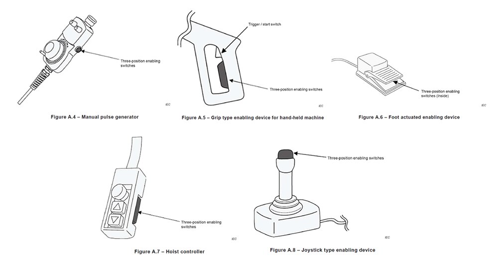
Please refer to this page for the enabling switches that can be used for these applications.
Enabling Switch Product Descriptions


